Sunday, October 14, 2018

WEEK 10 (FYP 2)

WEEK 10 : New Block Diagram and Flowchart

OBJECTIVE :
To redesign the block diagram and flowchart

METHODOLOGY :
The block diagram and flowchart was redesign based on the new specification of the project and my capability after doing some research on the internet.

RESULT:
Figure 36: New Block Diagram

Figure 37 : New Flowchart

ANALYSIS AND DISCUSSION :
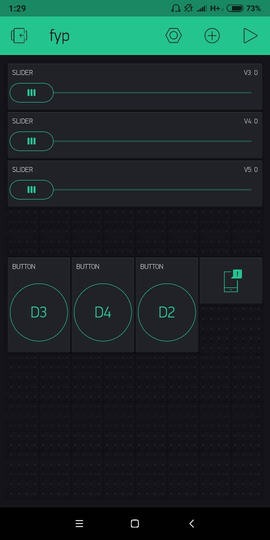
The block  consists of main power supply, smartphone application, internet access, WiFi, 3G, LED as the lamp,DC motor as a fan, motorized for door and curtain. PIR motion sensor for detection at home. This project is direct voltage supply 5V from usb cable connect with laptop. Internet is must turn on so, the smartphone application can function well. Then, the application must connect to the right server so that the application can connect to the main component with the server with the auth token and password. There have home appliances at the output side. For smartphone application display, the LED light and DC motor were display the On/Off button. Meanwhile, for door and curtain display the slider. Last but not least, for PIR motion were display the notification.

For the flowchart, Start from PIR motion sensor, If there is a movement, the LED inside the Blynk application will be turn ON, while if there's no movement, the LED inside that application will be turn OFF. Next, user can set up the timer for LED to turn ON and OFF. Furthermore, when the set up LED is ON (7am-7pm) the LDR sensor will trigger and send signal to the LED in the Blynk aplication for the user to monitor. When the time is not at 7am-7pm, all the LED will turn OFF.

CONCLUSION :
Finally, I was able to redesign my project based on my capability.  

WEEK 9 (FYP 2)

WEEK 9 : NodeMCU Burn

OBJECTIVE :
To make a two way in home automation system with installing a switch in the system.

METHODOLOGY :
Trying to install a direct switch on the led to make a 2 way.

RESULT:
Figure 35 : Node MCU did not function 


ANALYSIS AND DISCUSSION :
After installing a direct switch on the led, NodeMCU is burn. All of the system cannot function anymore.


CONCLUSION :
As conclusion, I decided to redesign new block diagram and flowchart for my project based on my capability.

WEEK 8 (FYP 2)

WEEK 8 : Combine Coding

OBJECTIVE :
To combine all the sketches in one.

METHODOLOGY:
1) Combine the coding in a proper way.
2) Test the coding on the project.

RESULT :


Figure 34: Full coding for my project

DISCUSSION AND ANALYSIS :
During combining sketches, we must make sure that there has no error to prevent from the bugs.

CONCLUSION :
As the conclusion, the project need almost 5 to 6 weeks to fully combining.


WEEK 7 (FYP 2 )

WEEK 7 : Test Servo Motor

OBJECTIVE :
To test the functionality of servo motor.

METHODOLOGY :
1) Set up coding for this part.
2) Set the virtual write inside coding.
2) Set up circuit with the right connection.
3) Connect NodeMCU with WiFi by using blynk application.

RESULT :

Video 7: Servo motor is function well.

Figure 31: Set up slider inside the blynk application

Figure 32: Make sure the value of output is between 0-180

Figure 33: Set virtual based on coding


ANALYSIS AND DISCUSSION :
Servo motor have 3 pins. The first pin is connected to ground.The second pin is connected to 3.3V NodeMCU while the third pins is connected to D0-D8 nodeMCU. The blynk must be set up correctly based on coding. For example, if one of three pins for servo motor was setting as D0 inside the coding, we must also set the virtual for the pins so that the blynk application can read the virtual to get the servo motor can be function.

CONCLUSION :
Make sure all the step has been set up correctly. If not the motor will not be function.


WEEK 6 (FYP 2)

WEEK 6 : Test DC Motor

OBJECTIVE :
To test the functionality of DC motor in this project.

METHODOLOGY :
1) Set up coding for this part.
2) Set up circuit with the right connection.
3) Connect NodeMCU with WiFi by using blynk application.

RESULT:

Video 6 : DC motor can function well

ANALYSIS AND DISCUSSION :
During the test, IC L293D must be together with dc motor. L293D IC is a typical motor. Driver IC which allows the DC motor to drive on any direction. This IC consists of 16-pins which are used to control a a set of two DC motors instantaneously in any direction. It means, by using a L293D IC we can control two DC motors. Meanwhile, a motor driver is a little current amplifier. The function of motor drives is to take a low-current signal that can drive a motor.

CONCLUSION:
DC motor cannot directly connected to NodeMCU. It must have IC L293D with it. If not the DC motor will not be function.