WEEK 17 : Submit the report (Chapter 1-5)
OBJECTIVES:
1) To finalize the report for chapter 1 until 5.
2) To submit the report to supervisor.
METHODOLOGY:
1) Do all the correction before submit to supervisor.
2) Add some addition info that can give extra marks.
3) Complete all the report for last submission.
4) Ask the supervisor to check the report before the deadline of the report.
RESULT: Report was submitted to supervisor.
ANALYSIS AND DISCUSSION:
From this subject, I gained more knowledge and skill to write a good report that can give a good marks. Besides, I learn how to find a problem and solve the problem to finish up my FYP project and get more experience to analyze some journal
CONCLUSION:
By completing all this report, basically this is the last task of this subject. This subject made us get many information and knowledge that we can apply during working time later. We learned a lot during making the project. There are a lot of challenges during preparation of the project from final year project 1(FYP 1) until FYP 2 but, this is one of the best memories throughout studying at UniKL BMI.
Saturday, November 10, 2018
WEEK 16 (FYP2)
WEEK 16: Chapter 5 (Conclusion and Recommendation)

OBJECTIVE:
1) To make a conclusion of my project.
2) To find a recommendation to improve of my project.
METHODOLOGY:
1) Use an internet and journal to get information of my project.
2) Find the benefit of home automation system to present in my report.
3) Find the limitation for the system.
4) Think an idea as the recommendation of this project.
RESULT:

Figure 48: Example of chapter 5 for my project.
ANALYSIS AND DISCUSSION:
There are many benefits that we can get from home automation system but, there are also had a limitation in my project that I write in my report. On top of that, many recommendation that we can made to improve the system of this project.
CONCLUSION:
As the conclusion, all the conclusion has been conclude in the report and the recommendation has been described so that the report was fulfill all the requirement need from the university.
WEEK 15 (FYP 2)
WEEK 15 : Chapter 4 (Result and Discussion)
OBJECTIVE:
1) To make a result of my project.
2) To describe all of the function for each component.
2) To completed the project with the specified time.
METHODOLOGY:
1) Take every result for each components(part by part).
2) Make sure the coding synchronize with the component.
RESULT:

OBJECTIVE:
1) To make a result of my project.
2) To describe all of the function for each component.
2) To completed the project with the specified time.
METHODOLOGY:
1) Take every result for each components(part by part).
2) Make sure the coding synchronize with the component.
RESULT:

Figure 47: Example of chapter 4 in my report.
ANALYSIS AND DISCUSSION:
It can be summarize as the overall result of my project. In this chapter, the functionality for each of the components has been described in more details. The connection for each of the components also has been described too. This report result was nicely being write with an example for each part as an evidence during making this project.
CONCLUSION:
In conclusion, this chapter can describe all the result of my project and the objectives of the project was successfully achieved.
Friday, November 9, 2018
WEEK 14 (FYP 2)
WEEK 14 : Presentation Day
OBJECTIVE :
1) To present the poster and project to an assessor.
2) To know the feedback of my project from the assessor.
METHODOLOGY:
1) Explain about the project briefly to the assessor.
2) Show the poster to assessor for further process.
RESULT:


OBJECTIVE :
1) To present the poster and project to an assessor.
2) To know the feedback of my project from the assessor.
METHODOLOGY:
1) Explain about the project briefly to the assessor.
2) Show the poster to assessor for further process.
RESULT:

Figure 44: My project and poster is ready to present

Figure 45: After the presentation

Figure 46: My supervisor, Sir Zaki.
ANALYSIS AND DISCUSSION:
During the presentation, the development Internet of Things (IOT) application for home automation system is presented to the assessor. Everything is working as an expected based on the plan. All part and connection was explained to assessor in detail to make them understanding about my project .
CONCLUSION:
All result show as proof that this project was done successfully as planning and expected and can proceed to the next step which is a final report to fulfill the university requirements.
WEEK 13 (FYP 2)
WEEK 13: Poster For Presentation

OBJECTIVE:
To finish the poster for the presentation for A1 size.
METHODOLOGY:
Use power point 2013 to design the poster.
RESULT:

Figure 43: Poster of my project
ANALYSIS AND DISCUSSION:
Poster done based on the requirement need from the university.
CONCLUSION:
Basically after finish doing a poster, it show that the project is around the corner to be presented to the accessor. All the details was filled inside the poster as the reference for the accessor to refer during presentation.
WEEK 12 (FYP2)
WEEK 13 : Make a model for my project and install the hardware into the model
OBJECTIVE :
1) To make a housing cover for my project.
2) To solder my hardware on the strip board.
METHODOLOGY :
1) Prepare the foam board for my house model.
2) Cut the foam board based on house model design.
3) Use a hot glue gun to connect between the foam board.
4) Use a wallpaper to make the foam board is more attractive.
5) Soldering all the components into the strip board.
RESULT :


ANALYSIS AND DISCUSSION :
The connection on the strip board must be solder properly. Multimeter was used to test the connection. Then, solder pump was used to uninstall the lead nicely. When the solder part is done, install all the hardware in the house model properly. During install the wiring into the house model, it must be not too tight because it will disturb the system. For the model, hot glue gun was used and must not put the glue too much between the foam board. Knife was used during making the model to cut the foam board so that the foam board has a nice cutting. Last but not least, furniture was install inside the house model so that it will make my project more interesting.
CONCLUSION :
As the conclusion, the model and hardware is done properly within the time given.
OBJECTIVE :
1) To make a housing cover for my project.
2) To solder my hardware on the strip board.
METHODOLOGY :
1) Prepare the foam board for my house model.
2) Cut the foam board based on house model design.
3) Use a hot glue gun to connect between the foam board.
4) Use a wallpaper to make the foam board is more attractive.
5) Soldering all the components into the strip board.
RESULT :

Figure 40: The house model is completely done

Figure 41: Furniture is install inside the house model

Figure 42: The hardware is install properly inside the house model
ANALYSIS AND DISCUSSION :
The connection on the strip board must be solder properly. Multimeter was used to test the connection. Then, solder pump was used to uninstall the lead nicely. When the solder part is done, install all the hardware in the house model properly. During install the wiring into the house model, it must be not too tight because it will disturb the system. For the model, hot glue gun was used and must not put the glue too much between the foam board. Knife was used during making the model to cut the foam board so that the foam board has a nice cutting. Last but not least, furniture was install inside the house model so that it will make my project more interesting.
CONCLUSION :
As the conclusion, the model and hardware is done properly within the time given.
WEEK 11 (FYP 2)
WEEK 12 : Set up new hardware
OBJECTIVE:
1) To build my final year project based on the new hardware.
2) To determine my new project hardware is completely function.
METHODOLOGY:
1) Connect the PIR sensor at D6 node MCU pin.
2) Connect the LDR 1,2 and 3 sensor at
3) Connect LED 1,2 and 3 at pin
4) Set up Blynk application for this project.
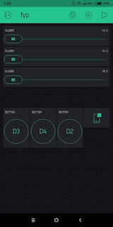
5) Add 3 buttons, 4 LED and 1 timer in the Blynk application.
RESULT :

ANALYSIS AND DISCUSSION :
When there has a movement on the PIR Sensor, the signal will trigger and will turn ON the LED in the Blynk application. User can set up timer to turn ON three LED. When the LED is ON, it will trigger the LDR sensor and will send the signal to the Blynk application. The LED on the Blynk application that represent the home appliances will turn ON.
CONCLUSION:
As the conclusion, the new hardware function successfully.
OBJECTIVE:
1) To build my final year project based on the new hardware.
2) To determine my new project hardware is completely function.
METHODOLOGY:
1) Connect the PIR sensor at D6 node MCU pin.
2) Connect the LDR 1,2 and 3 sensor at
3) Connect LED 1,2 and 3 at pin
4) Set up Blynk application for this project.
5) Add 3 buttons, 4 LED and 1 timer in the Blynk application.
RESULT :

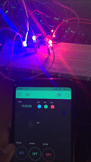
Figure 38: New hardware of my project.

Figure 39: New project is functioning well
When there has a movement on the PIR Sensor, the signal will trigger and will turn ON the LED in the Blynk application. User can set up timer to turn ON three LED. When the LED is ON, it will trigger the LDR sensor and will send the signal to the Blynk application. The LED on the Blynk application that represent the home appliances will turn ON.
CONCLUSION:
As the conclusion, the new hardware function successfully.
Sunday, October 14, 2018
WEEK 10 (FYP 2)
WEEK 10 : New Block Diagram and Flowchart
OBJECTIVE :
To redesign the block diagram and flowchart
METHODOLOGY :
The block diagram and flowchart was redesign based on the new specification of the project and my capability after doing some research on the internet.
RESULT:


OBJECTIVE :
To redesign the block diagram and flowchart
METHODOLOGY :
The block diagram and flowchart was redesign based on the new specification of the project and my capability after doing some research on the internet.
RESULT:

Figure 36: New Block Diagram

Figure 37 : New Flowchart
ANALYSIS AND DISCUSSION :
The block consists of main power supply, smartphone application, internet access, WiFi, 3G, LED as the lamp,DC motor as a fan, motorized for door and curtain. PIR motion sensor for detection at home. This project is direct voltage supply 5V from usb cable connect with laptop. Internet is must turn on so, the smartphone application can function well. Then, the application must connect to the right server so that the application can connect to the main component with the server with the auth token and password. There have home appliances at the output side. For smartphone application display, the LED light and DC motor were display the On/Off button. Meanwhile, for door and curtain display the slider. Last but not least, for PIR motion were display the notification.
For the flowchart, Start from PIR motion sensor, If there is a movement, the LED inside the Blynk application will be turn ON, while if there's no movement, the LED inside that application will be turn OFF. Next, user can set up the timer for LED to turn ON and OFF. Furthermore, when the set up LED is ON (7am-7pm) the LDR sensor will trigger and send signal to the LED in the Blynk aplication for the user to monitor. When the time is not at 7am-7pm, all the LED will turn OFF.
For the flowchart, Start from PIR motion sensor, If there is a movement, the LED inside the Blynk application will be turn ON, while if there's no movement, the LED inside that application will be turn OFF. Next, user can set up the timer for LED to turn ON and OFF. Furthermore, when the set up LED is ON (7am-7pm) the LDR sensor will trigger and send signal to the LED in the Blynk aplication for the user to monitor. When the time is not at 7am-7pm, all the LED will turn OFF.
CONCLUSION :
Finally, I was able to redesign my project based on my capability.
WEEK 9 (FYP 2)
WEEK 9 : NodeMCU Burn
OBJECTIVE :
To make a two way in home automation system with installing a switch in the system.
METHODOLOGY :
Trying to install a direct switch on the led to make a 2 way.
RESULT:

ANALYSIS AND DISCUSSION :
After installing a direct switch on the led, NodeMCU is burn. All of the system cannot function anymore.
CONCLUSION :
As conclusion, I decided to redesign new block diagram and flowchart for my project based on my capability.
OBJECTIVE :
To make a two way in home automation system with installing a switch in the system.
METHODOLOGY :
Trying to install a direct switch on the led to make a 2 way.
RESULT:

Figure 35 : Node MCU did not function
ANALYSIS AND DISCUSSION :
After installing a direct switch on the led, NodeMCU is burn. All of the system cannot function anymore.
CONCLUSION :
As conclusion, I decided to redesign new block diagram and flowchart for my project based on my capability.
WEEK 8 (FYP 2)
WEEK 8 : Combine Coding
OBJECTIVE :
To combine all the sketches in one.
METHODOLOGY:
1) Combine the coding in a proper way.
2) Test the coding on the project.
RESULT :


OBJECTIVE :
To combine all the sketches in one.
METHODOLOGY:
1) Combine the coding in a proper way.
2) Test the coding on the project.
RESULT :


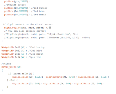
Figure 34: Full coding for my project
DISCUSSION AND ANALYSIS :
During combining sketches, we must make sure that there has no error to prevent from the bugs.
CONCLUSION :
As the conclusion, the project need almost 5 to 6 weeks to fully combining.
WEEK 7 (FYP 2 )
WEEK 7 : Test Servo Motor
OBJECTIVE :
To test the functionality of servo motor.
METHODOLOGY :
1) Set up coding for this part.
2) Set the virtual write inside coding.
2) Set up circuit with the right connection.
3) Connect NodeMCU with WiFi by using blynk application.
RESULT :


ANALYSIS AND DISCUSSION :
Servo motor have 3 pins. The first pin is connected to ground.The second pin is connected to 3.3V NodeMCU while the third pins is connected to D0-D8 nodeMCU. The blynk must be set up correctly based on coding. For example, if one of three pins for servo motor was setting as D0 inside the coding, we must also set the virtual for the pins so that the blynk application can read the virtual to get the servo motor can be function.
CONCLUSION :
Make sure all the step has been set up correctly. If not the motor will not be function.
OBJECTIVE :
To test the functionality of servo motor.
METHODOLOGY :
1) Set up coding for this part.
2) Set the virtual write inside coding.
2) Set up circuit with the right connection.
3) Connect NodeMCU with WiFi by using blynk application.
RESULT :
Video 7: Servo motor is function well.
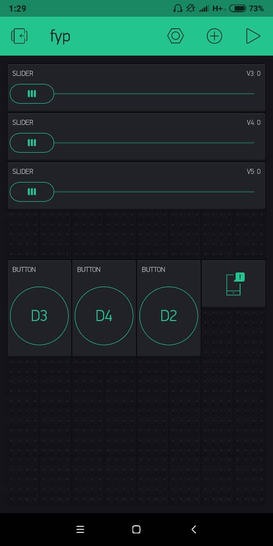
Figure 31: Set up slider inside the blynk application

Figure 32: Make sure the value of output is between 0-180

Figure 33: Set virtual based on coding
ANALYSIS AND DISCUSSION :
Servo motor have 3 pins. The first pin is connected to ground.The second pin is connected to 3.3V NodeMCU while the third pins is connected to D0-D8 nodeMCU. The blynk must be set up correctly based on coding. For example, if one of three pins for servo motor was setting as D0 inside the coding, we must also set the virtual for the pins so that the blynk application can read the virtual to get the servo motor can be function.
CONCLUSION :
Make sure all the step has been set up correctly. If not the motor will not be function.
WEEK 6 (FYP 2)
WEEK 6 : Test DC Motor
OBJECTIVE :
To test the functionality of DC motor in this project.
METHODOLOGY :
1) Set up coding for this part.
2) Set up circuit with the right connection.
3) Connect NodeMCU with WiFi by using blynk application.
RESULT:
During the test, IC L293D must be together with dc motor. L293D IC is a typical motor. Driver IC which allows the DC motor to drive on any direction. This IC consists of 16-pins which are used to control a a set of two DC motors instantaneously in any direction. It means, by using a L293D IC we can control two DC motors. Meanwhile, a motor driver is a little current amplifier. The function of motor drives is to take a low-current signal that can drive a motor.
CONCLUSION:
DC motor cannot directly connected to NodeMCU. It must have IC L293D with it. If not the DC motor will not be function.
OBJECTIVE :
To test the functionality of DC motor in this project.
METHODOLOGY :
1) Set up coding for this part.
2) Set up circuit with the right connection.
3) Connect NodeMCU with WiFi by using blynk application.
RESULT:
Video 6 : DC motor can function well
ANALYSIS AND DISCUSSION :During the test, IC L293D must be together with dc motor. L293D IC is a typical motor. Driver IC which allows the DC motor to drive on any direction. This IC consists of 16-pins which are used to control a a set of two DC motors instantaneously in any direction. It means, by using a L293D IC we can control two DC motors. Meanwhile, a motor driver is a little current amplifier. The function of motor drives is to take a low-current signal that can drive a motor.
CONCLUSION:
DC motor cannot directly connected to NodeMCU. It must have IC L293D with it. If not the DC motor will not be function.
Monday, August 20, 2018
WEEK 5 (FYP 2)
WEEK 5 : Test PIR Motion Sensor
OBJECTIVE :
To test functionality of the PIR Motion Sensor .
METHODOLOGY :
1) set up coding.
2) Check in the Arduino software serial monitor.
RESULT :
ANALYSIS & DISCUSSION :
Make sure PIR Motion Sensor terminal rightly connected with the Node MCU port.
CONCLUSION :
The PIR Motion Sensor is working vey well.
OBJECTIVE :
To test functionality of the PIR Motion Sensor .
METHODOLOGY :
1) set up coding.
2) Check in the Arduino software serial monitor.
RESULT :
Video 5 : PIR Motion Sensor can function.
ANALYSIS & DISCUSSION :
Make sure PIR Motion Sensor terminal rightly connected with the Node MCU port.
CONCLUSION :
The PIR Motion Sensor is working vey well.
WEEK 4 (FYP 2)
WEEK 4 : Testing LED With Blynk Application
OBJECTIVE :
1) To determine functionality of the LED to connect with blynk apps.
2) To test two port Node MCU to connect with LED in parallel connection.
METHODOLOGY :
1) Node MCU connect with WiFi and setting through blynk apps.
2) Set up coding with the right WiFi SSID and passwaord.
3) Set up circuit with the right connection.
RESULT :
DISCUSSION & ANALYSIS :
During the first test, the LED do not turn ON because NodeMCU cannot be connected to WiFi. The important things in this process is make sure the LED terminal are connected correctly. The positive terminal should connect with Node MCU port and the negative terminal connect with grounding.
CONCLUSION :
All the objectives is achieved.
OBJECTIVE :
1) To determine functionality of the LED to connect with blynk apps.
2) To test two port Node MCU to connect with LED in parallel connection.
METHODOLOGY :
1) Node MCU connect with WiFi and setting through blynk apps.
2) Set up coding with the right WiFi SSID and passwaord.
3) Set up circuit with the right connection.
RESULT :
Video 3 : LED do not function (do not turn ON) at first trial
Video 4 : LED is function well
DISCUSSION & ANALYSIS :
During the first test, the LED do not turn ON because NodeMCU cannot be connected to WiFi. The important things in this process is make sure the LED terminal are connected correctly. The positive terminal should connect with Node MCU port and the negative terminal connect with grounding.
CONCLUSION :
All the objectives is achieved.
Thursday, August 16, 2018
WEEK 3 (FYP 2)
WEEK 3 : Testing NodeMCU (ESP8266)
OBJECTIVE :
1) To find the right NodeMCU.
2) To Test the blynk application.
METHODOLOGY :
1) Test the Node MCU using serial monitor in Arduino software.
2) Test blynk apps on Android smartphone.
Results :
Video 1 : Node MCU cannot connect WiFi
Video 2 : Node MCU can connected to WiFi.
 Figure 28 : Serial monitor from the first Node MCU
 Figure 29 : Serial monitor from the second Node MCU


Discussion & Analysis :
In video 1, the first Node MCU cannot connect to the WiFi, while in video 2, the second Node MCU easily can connected to the WiFi. In a picture 1, we can see from the serial monitor in Arduino software, the first Node MCU cannot connect to the WiFi, while in the second picture, the serial monitor can connect to the WiFi.
Conclusion :
We need to test every hardware that we buy to ensure the hardware is working properly.
Tuesday, August 14, 2018
WEEK 2 (FYP 2)
WEEK 2 : Compare The Price Of The Components
OBJECTIVE :
1) To avoid paying higher price to the seller.
2) To identify the best price of the components between store.
METHODOLOGY :
1) Identify the store that sell the components.
2) Visit the stores and make the comparison of the price.
3) Searching the price at online store.
RESULT :
I found the components that I want in various price.
ANALYSIS & DISCUSSION :
1) Get to find the product in range of budget.
2) Get to find the product in lowest price.
CONCLUSION :
The objective is achieved because I get identify the lowest price between the stores.
WEEK 1 (FYP 2 )
WEEK 1 : Meeting With Supervisor To Show List Of Hardware
OBJECTIVE :
1) To clarify the hardware need to use in the project.
2) To show the list of hardware that need to buy.
METHODOLOGY :
Show all the hardware that are listed to supervisor.
RESULT :

ANALYSIS & DISCUSSION :
1) All the hardware listed is already confirm by supervisor.
2) Item need in the hardware setup has been minimize for the project.
CONCLUSION :
The objective is achieved and basically all the hardware need for setup the hardware is already done.
OBJECTIVE :
1) To clarify the hardware need to use in the project.
2) To show the list of hardware that need to buy.
METHODOLOGY :
Show all the hardware that are listed to supervisor.
RESULT :

Figure 27 : List of hardware that use in this project
ANALYSIS & DISCUSSION :
1) All the hardware listed is already confirm by supervisor.
2) Item need in the hardware setup has been minimize for the project.
CONCLUSION :
The objective is achieved and basically all the hardware need for setup the hardware is already done.
Thursday, May 24, 2018
WEEK 17
WEEK 17 : Submit proposal and draft of chapter 1,2 and 3
OBJECTIVE:
1) To finalize the proposal and draft for chapter 1-3 for submission.
2) To submit the report to supervisor.
METHODOLOGY:
1) Do all the correction and repair the proposal before final submission.
2) Add some addition info that can give an extra marks.
3) Complete all the proposal and the draft for last submission.
4) Send the proposal, draft and the slide at VLE
RESULT:
1) All the report writing is completed before final submission.
2) All the blog writing is completed before submission.


From this subject, I understand more to write a good report that can give a good marks. After finish the submission as to fulfill the institution requirement, all the students need to concentrated on settle the hardware and software for the next semester.
CONCLUSION :
By completing all this proposal and draft for the chapter 1-3, basically this subject is finish for this semester. However, this blog will continue on next semester under FYP 2.
OBJECTIVE:
1) To finalize the proposal and draft for chapter 1-3 for submission.
2) To submit the report to supervisor.
METHODOLOGY:
1) Do all the correction and repair the proposal before final submission.
2) Add some addition info that can give an extra marks.
3) Complete all the proposal and the draft for last submission.
4) Send the proposal, draft and the slide at VLE
RESULT:
1) All the report writing is completed before final submission.
2) All the blog writing is completed before submission.

Figure 23: FYP 1 Proposal

Figure 24: FYP 1 Report (chapter1-3)

Figure 25: FYP 1 Slide
 Figure 26: Blog (fyprushdeenasyibra76.blogspot.my)
ANALYSIS AND DISCUSSION :
From this subject, I understand more to write a good report that can give a good marks. After finish the submission as to fulfill the institution requirement, all the students need to concentrated on settle the hardware and software for the next semester.
CONCLUSION :
By completing all this proposal and draft for the chapter 1-3, basically this subject is finish for this semester. However, this blog will continue on next semester under FYP 2.
WEEK 16
WEEK 16 : CHAPTER 3 (METHODOLOGY)
OBJECTIVES :
1) To know the whole operations that used in this project.
2) To identify the function for each of the component.
3) To completed the project with the specified time.
METHODOLOGY:
1) Built a gantt chart for FYP 1 and the expected gantt chart for the FYP 2.
2) Built a block diagram and flowchart to make a better understanding for this project.
3) Meet the supervisor and ask him to check whether it is correct or not.
RESULT :

Figure 19: Gantt chart FYP 1

Figure 20: Gantt chart FYP 2

Figure 21: Block diagram

Figure 22: Flowchart
ANALYSIS AND DISCUSSION :
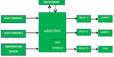
All the activities that are listed in Gantt chart is mentioned by Sir Zaki. For the block diagram, in short, there have two sensor used. The first sensor is light
sensor as a sensor to detect the light. The second one is temperature sensor which is will
be function to detect the temperature of surroundings. The Arduino board that used for the project is
NodeMCU. In the output side, there have a relay for each types of home devices
which are two lamps and a fan. The flowchart is explained from the beginning and then, when the timer at 7pm or 7am , it will check the status of the home appliances which is lamp and fan. After that, it will pass through a relay and then when the time at 7pm the appliances will ON. If the time at 7am the appliances will OFF. However, if the time is not in the specified time, it will receive the signal from Blynk and then it will check the status for each appliances. After receiving the signal, the status will send to the phone.
CONCLUSION :
In this project, we know the whole operations that used in this project. Further than that, we can identify the function for each component. Lastly, we can completed the project with the specified time.
WEEK 15
WEEK 15: CHAPTER 2 (LITERATURE REVIEW)
OBJECTIVES:
1) To know the history of smart home in detail.
2) To gain more knowledge from different types of journal.
3) To know the various operations for this project from various method.
METHODOLOGY:
1) Find the suitable journal that related with this project.
2) Read the journal carefully.
3) List down all the important point as the addition information to this project.
RESULT :
1 The first journal that I found is David, N., Chima, A., Ugochukwu, A., &
Obinna, E. (2015). Design of a home automation system using arduino. International
Journal of Scientific & Engineering Research, 6(6),
795-801.
The second journal is Jain, S., Vaibhav, A., & Goyal, L. (2014,
February). Raspberry Pi based interactive home automation system through
E-mail. In Optimization, Reliabilty, and Information Technology
(ICROIT), 2014 International Conference on (pp. 277-280). IEEE. The purpose of the journal is to design basic
home automation application on Raspberry Pi through reading the subject of
Email and the algorithm for the same.
Last journal in my research is Jivani,
M. N. (2014). Gsm based home automation system using app-inventor for Android
mobile phone. International Journal of Advanced Research in Electrical,
Electronics and Instrumentation Engineering, 3(9). For this journal, the App-Inventor is to make
programming enjoyable and accessible to novices. GSM based Device Control
System mobile application developed using the App-Inventor for Android smart
phone will be beneficial for the masses.
ANALYSIS AND DISCUSSION :
In the first journal, it used temperature sensor , PIR sensor, Light sensor, Gas sensor, relay switch,
Arduino microcontroller Atmega 2560, and web portal. The project is low cost and flexible home
control and monitoring system. However, Arduino can sense the surroundings by
receiving input signal from variety of sensor. Besides, the temperature sensor
is fairly simple to use but required careful timing to grab data.
Next journal are using Modem, Raspberry Pi, relay and
electronic device. In this project, the operations is Raspberry Pi has been
chosen as the processing unit. Python coded algorithm has been fed into the
Raspberry Pi and connected to the internet through modem. Besides, the relay
will control the high voltage for the output to control from burn. This
Raspberry Pi are user friendly features and economical benefits but it is too
expensive compare to the Arduino.
The last journal is are using Arduino microcontroller, GSM module,
peripheral driver, relay, mobile phone and appliances. In this project, the
Arduino will connected to the GSM network through GSM module. By using GSM, no need data internet to send
the command to the Arduino. Furthermore, it can make call and send short
message but it require credit to make call and send the message and it is not
simply to use.
CONCLUSION:
The conclusion is we get to know the history of smart home in detail. We also gain more knowledge from different types of journal. Last but not least, we know the various operations for this project from various method.
WEEK 14
WEEK 14 : CHAPTER 1 (INTRODUCTION)
OBJECTIVES :
1) To describe all the main purpose in this project.
2) To further the understanding of the reader.
3) To identify the benefit of this project for the user
METHODOLOGY :
1) Do some research that can be obtained at the website or any blog.
2) List the main point which is consists of objectives of the project, problem statements, expectation outcome, scope and limitation.
RESULTS :
1) Objective of Project :
3) Expectation outcome :

4) Scope and limitation :
Scope :
Limitation :
OBJECTIVES :
1) To describe all the main purpose in this project.
2) To further the understanding of the reader.
3) To identify the benefit of this project for the user
METHODOLOGY :
1) Do some research that can be obtained at the website or any blog.
2) List the main point which is consists of objectives of the project, problem statements, expectation outcome, scope and limitation.
RESULTS :
1) Objective of Project :
- To monitor and control home appliances using Arduino.
- To design two way communication system between the house-hold appliances and user’s controlling device.
- To let the users get information using blynk application.
People
nowadays, facing the problem of electricity consumption. For example, when they
forgot to switch off any home devices, they will waste the electricity at their
home. For other cases, elderly or physically handicapped person, they have a
difficulty to control ON or OFF switches in their home since it is difficult
for them to control it. Last but not least, people will waste their time to
check the status of the light outside their home and they need to control the
ON or OFF switches even when they are on their bed.

Figure 18 : Expectation outcome
4) Scope and limitation :
Scope :
The scope of this project is to control and
monitor smart home system by utilizing Arduino NodeMCU connected to the device
and relay to give output of this home automation system. Besides, the scope of
this project is to develop home automation system using blynk application. It
can used to replace all the switches for the home appliances in the house.
1) Learning difficulty
There
will always have some people that are hard to catch fast when they are learning
something new. This will may take a lot of time for them to understand the
procedure when using that system.
2) Reliability
Smart
home system will be very dependent to the internet. This can be a problem
because if connection of the internet is disconnected, the users cannot monitor
the appliances in the house. Other than that, it can be possibly occur if there
have an interruption between the wireless signal and other home appliances so,
the system will automatically become slowly.
ANALYSIS & DISCUSSION:
CONCLUSION:
It can be summarize as introducing to the project with a few specifications in terms of project background, problem statements, objectives, expectation outcome, scope and limitation. The project background is about the process of the system that available in this project.
In conclusion, this chapter can describe all the main purpose in this project. On top of that, it can further the understanding of the reader and identify the benefit of this project for the user.
Saturday, April 14, 2018
WEEK 13
WEEK 13 : Presentation Day
Objective :
1) To present the slide to an assessor.
2) To know the feedback about the project from assessor.
Methodology :
Result :
1) Assessors gives their suggestion and idea to enhance this project
2) Assessors understanding about the whole system of this project.


Analysis & Discussion :
Conclusion : By presenting to the assessor, the project is approved and can be proceed to the next step. My explanation of the running project are very well and can be understood.
Objective :
1) To present the slide to an assessor.
2) To know the feedback about the project from assessor.
Methodology :
1) Explain about the project briefly to the assessor.
2) Show the slide to accessor for further process and method use to complete the project.
Result :
1) Assessors gives their suggestion and idea to enhance this project
2) Assessors understanding about the whole system of this project.

Figure 16: With my supervisor Sir Zaki Abdul Karim

Figure 17: After the presentation
Analysis & Discussion :
During presentation day, there are several part that I need to re do again. The advises from my assessors which is to find the suitable problem statements so that the project can be improved upon. Other than that, they also reprimand my mistakes in operation part which is consists of block diagram and flowchart.
WEEK 12
WEEK 12 : Generate Costing
Objective :
1) To control the expenditure of the hardware to be used in this project based on affordable budget.
1) To control the expenditure of the hardware to be used in this project based on affordable budget.
2) To make it easier for all the students to claim their money with their institution without any problems.
Methodology :
1) Estimate the budget that can be spend for FYP 1.
2) Do a research about the suitable hardware that can used.
3) List all the hardware and their price in a table.
2) Do a research about the suitable hardware that can used.
3) List all the hardware and their price in a table.
Result :

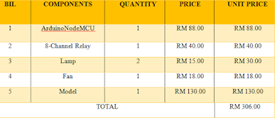
Figure 15 : The estimated budget for my project
Analysis & Discussion :
The estimated budget is simply I get from website and google everything about the hardware and the price. S, I simply estimated that the price will be around RM306.00. Even though our institution provide RM 500 for their students but basically, this is all I need in my project.
Conclusion : It is very important to get a handle on cost estimation. This is because when money-based problems come up, this will help when come to the end of the project.
WEEK 11
WEEK 11 : Produce Gantt Chart
Objective :
1)To fulfill all the plan that have be done in final year project 1.
2) To illustrate how the project will run.
Methodology :
1) List all the activities that have be done along for this project.
2) Create a suitable gantt chart that can easy to understand.
Result :

Figure 13 : Gantt chart FYP 1

Analysis & Discussion : The time frame allocated for this research study is 17 weeks. It started in January 2018 and is projected to be completed in May 2018.
Conclusion : As the conclusion, all the detail about the Gantt chart is showing. Gantt chart is important as part of planning to drive me to finish the project on time.
Objective :
1)To fulfill all the plan that have be done in final year project 1.
2) To illustrate how the project will run.
Methodology :
1) List all the activities that have be done along for this project.
2) Create a suitable gantt chart that can easy to understand.
Result :


Figure 14: Gantt chart FYP 2
Analysis & Discussion : The time frame allocated for this research study is 17 weeks. It started in January 2018 and is projected to be completed in May 2018.
WEEK 10
WEEK 10 : Feasibility Study
Objective : To check whether the project is easy to make or not.
Methodology :
1) Check the prices on the internet about the equipment to be used in this project.
2) Make a research on how to get all the equipment.
3) Check the place that sells the equipment.
Results :
Analysis & Discussion :
Conclusion : As the conclusion, I can proceed with this project for final year project because it is easy to make and there is no problem in terms of making hardware.
Objective : To check whether the project is easy to make or not.
Methodology :
1) Check the prices on the internet about the equipment to be used in this project.
2) Make a research on how to get all the equipment.
3) Check the place that sells the equipment.
Results :
In general, this project has no problem being made because there are several reasons. First, the project is not very expensive because the materials used are all reasonable. Second, the material for this project is easy to get because the store selling such materials is not too far from this university, and does not have to buy online. Moreover, this project uses android directly. It is not a problem for the user as there are many phone users using a phone that has android
Analysis & Discussion :
In this project, the controller board that is used is Arduino NodeMCU. The cost of this components is not expensive than Raspberry Pi and so forth. So it is worth to develop this project without any probelms. Further than that, we can easily find the hardware at the store. Lastly, there are many android user so we do not need to worry.
Conclusion : As the conclusion, I can proceed with this project for final year project because it is easy to make and there is no problem in terms of making hardware.
WEEK 9
WEEK 9 : Describe Input And Output Controller
Objective : To know the suitable input and output for my project.
Methodology :
1) Searching an internet about this project.
2) Meet supervisor and ask him to check whether its correct or not.
3) Looking at the blog from the previous student.
Results :

Analysis & Discussion :
Blynk app :
Wifi module :
Conclusion : I understand more about my project and can proceed to the next step.
Objective : To know the suitable input and output for my project.
Methodology :
1) Searching an internet about this project.
2) Meet supervisor and ask him to check whether its correct or not.
3) Looking at the blog from the previous student.
Results :

Figure 12: Blynk app
Analysis & Discussion :
Blynk app :
Blynk app was designed for the Internet of Things. It can control hardware remotely, it can store data, and do many other cool things. It's really simple to set everything up and will start tinkering in less than 5 minutes. Its supporting hardware of my choice which is the Arduino is linked to the ESP8266 chip.
For the input, WiFi module will sent data we want to Arduino.
For the process, it will be used for collecting data from the WiFi module and then it will process the data and send the data to the relay.
For the output, there is a relay to control the high voltage for the output. If we do not control the output, the output may be burn. The reason is Arduino cannot control high voltage and ampere, but a relay can do this job which is the sole design of it. So, we are using relay as switch to control high power devices.
Conclusion : I understand more about my project and can proceed to the next step.
Monday, April 9, 2018
WEEK 8
WEEK 8 : Design Block Diagram
Objective : To identify overall system of the project.
Methodology : Make some research on this block diagram by asking my supervisor as well and searching at the internet.
Result :

Objective : To identify overall system of the project.
Methodology : Make some research on this block diagram by asking my supervisor as well and searching at the internet.
Result :

Figure 11: Block Diagram
Analysis and Discussion :
There have two sensor used. The first sensor is light sensor as a sensor to detect the light. The second one is temperature sensor which is will be function to detect the temperature of surroundings. The Arduino board that used for the project is NodeMCU. In the output side, there have a relay for each types of home devices which are two lamps and a fan.
Conclusion :
Finally, I was able to identify how the project works.
Sunday, March 18, 2018
WEEK 7
WEEK 7 : Set Up Objectives For Final Year Project
Objective : To identify the objectives that I want to achieve in this project.
Methodology :
1) Do a research for this project to get the objectives I want to achieve.
2) Watch many videos in youtube that related to my project to make it easier for me to identify the objectives for this project.
Result :
This research study intends to plug the research gap and will demonstrate the development of the home automation system with Android based remote control by :
Discussion & Analysis :
Conclusion : All the objectives have been achieved.
Objective : To identify the objectives that I want to achieve in this project.
Methodology :
1) Do a research for this project to get the objectives I want to achieve.
2) Watch many videos in youtube that related to my project to make it easier for me to identify the objectives for this project.
Result :
This research study intends to plug the research gap and will demonstrate the development of the home automation system with Android based remote control by :
- To monitor and control home appliances using Arduino.
- To design two-way communication system between the house-hold appliances and user's controlling device.
- To get the information using blynk app.
Discussion & Analysis :
Arduino is a device that used to controlling the lights, motors and various physical. These devices can directly use a USB cable. Arduino uses a simplified version of C++, making it simple to learn program. Next, a two-way communication system can determine whether the output is on or off. The system occurs when the receiver provides feedback to the sender. For the blynk app,it allow to create amazing interfaces for the projects using various widgets which are provided.
Conclusion : All the objectives have been achieved.
Monday, March 12, 2018
WEEK 6
WEEK 6 : Benchmarks For Final Year Project
Objective :
1) To find out various ways to control home automation system.
2) To identify the advantages and disadvantages in every way used.
Methodology :
1) Find information on projects that have been done on the internet.
2) See the advantages and disadvantages of each project.
3) List 3 ways to control home automation system that people usually make for their projects.
4) Make a comparison between 3 projects.
Results :
1) Android : https://www.youtube.com/watch?v=iX2hvJXF7Qo

2) GSM : https://www.youtube.com/watch?v=a1LaE7oRfAA

3) Bluetooth : https://www.youtube.com/watch?v=MnaryeiBStM

Analysis & Discussion :
I have found 3 ways to control home automation system :
1) Android
2) Global System for Mobile (GSM)
3) Bluetooth
Conclusion :
I have learnt a lot of things through comparison between projects so that from that I can make a better project and improve the deficiencies in the project.
Objective :
1) To find out various ways to control home automation system.
2) To identify the advantages and disadvantages in every way used.
Methodology :
1) Find information on projects that have been done on the internet.
2) See the advantages and disadvantages of each project.
3) List 3 ways to control home automation system that people usually make for their projects.
4) Make a comparison between 3 projects.
Results :
1) Android : https://www.youtube.com/watch?v=iX2hvJXF7Qo

Figure 8: Home automation system using Android

Figure 9: Home automation system using GSM
3) Bluetooth : https://www.youtube.com/watch?v=MnaryeiBStM

Figure 10: Home automation system using bluetooth
Analysis & Discussion :
I have found 3 ways to control home automation system :
1) Android
Android application meaning we have a smartphone which has got the android operating system and one we switch on the button the bulb will on. There is a pro and cons in this project which is for the pro, it can save cost because the apps that need to be used are free.Besides, many people nowadays use android phones, so this makes it easy for the project maker. The apps also are more attractive and have multiple function. For the cons, it required internet access, so the apps are always working.
2) Global System for Mobile (GSM)
In this project, GSM wireless communication is used for controlling home appliances. It send some commands for controlling AC home appliances. After receiving given commands by Arduino through GSM , Arduino send signal to relays, to switch ON or OFF the home appliances using a relay driver. There is pro and cons which is for the pro it can make calls and send short messages. For the cons, it requires credit to make calls and send messages, thus requiring a lot of spending. Besides, has limited functionality.
In this project, it use step down transformer and then Arduino Uno R3 connected to the bluetooth module. After that, it use 4 relay connected to 3 bulbs AC bulb and another relay connected to DC fan. There is pro and cons which is for the pro it do not require internet data. By using bluetooth, it will saving cost because it does not require credit to get function but the distance required for the bluetooth to work is very minimal - only 10 to 15 meters.
Conclusion :
I have learnt a lot of things through comparison between projects so that from that I can make a better project and improve the deficiencies in the project.
Monday, March 5, 2018
WEEK 5
WEEK 5 : Problem Statement
Objective :
1) To simplify the easy and convenient methods to control the appliances that are running
2) To make people lives easier by automatically monitor their switching on the lights.
3) To overcome safety problems over long distance.
4) To reduce the rate of power consumption by ensuring devices are only on when needed.
Methodology :
1) Do some research about my project by searching the internet.
2) Ask a few friends and family members about what they can see that can solve the problem by using home automation system.
3) Ask my supervisor on how my project is work and give benefit to the consumer from his opinion.
Result :

Figure 7 : Sir Zaki showing me how the system is running and letting out issues that can be solved.
Analysis & Discussion :
The main objective of this project is to design a home automation system that allows remote control characteristics in easing the controls of home appliances. Without this technology, user may face many problems in setting up a Home Automation System to control our home devices such as :
- Difficult for the elderly or physically handicapped people to on and off the switches which located at different place in the house.
- Waste our time in case ; need to wake up in night if we forget to switch off any devices that may be danger to our house.
- Waste electricity in case; forget to switch off any home devices at upstairs of double storey houses.
CONCLUSION :
For the conclusion, we can simplify the easy and convenient methods to control the appliances that are running. Then, we can make people lives easier by automatically monitor their switching on the lights. We also can overcome safety problems over long distance. Lastly, we can reduce the rate of power consumption by ensuring devices are only on when needed.
Sunday, February 18, 2018
WEEK 4
WEEK 4 : Registered Blog For Final Year Project
Objective :
1) To register my blog for FYP1 in website provided .
2) To let my supervisor easy to follow my project developer.
Methodology :
1) Meet advisor, Sir Ahmad Zaki to register my blog.
2) Inform my blog address to Sir Zaki.
3) Ask him about the suitability of the blog address.
Result :


Analysis & Discussion :
Conclusion :
Objective :
1) To register my blog for FYP1 in website provided .
2) To let my supervisor easy to follow my project developer.
Methodology :
1) Meet advisor, Sir Ahmad Zaki to register my blog.
2) Inform my blog address to Sir Zaki.
3) Ask him about the suitability of the blog address.
Result :

Figure 5 : Meeting session with Sir Zaki to register my blog for final year project.

Figure 6 : My officially blog
During our meeting session, Sir Zaki was disagreed with using the full name as my blog address. He told me to change the address name because it will make easier to me one day when I am going to create a new blog.
I have agreed to change my blog address from rushdeenasyibra.blogspot.my to fyprushdeenasyibra76.blogspot.my. It seems that this blog is specific to my final year project. Finally, my objective to register my blog was achieved.
Subscribe to:
Comments (Atom)